How To Make
Realistic Jewelry Renderings
Tutorial - How to Make Realistic Renderings
- Tutorial
- Page 1 - Introduction
- Page 2 - Modelling
- Page 3 - Materials
- Page 4 - Environment
- Page 5 - Video Post
- Page 6 - Conclusion
- Models ready for Jewelry Renderings
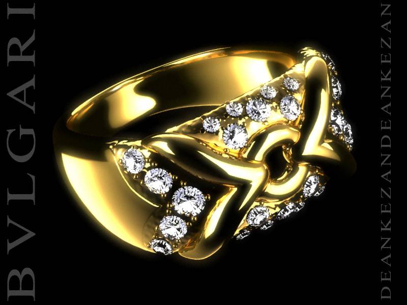
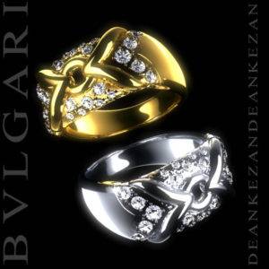
This tutorial will quide you to build diamond, BVLGARI ring TRIKA with its materials and video post renderings. This tutorial was made 2001 and it is still good one 😉
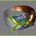
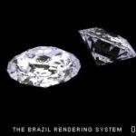
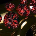
Some people asked me how I made this image, so I decided to show you some step by step instructions for building something similar. The image was made for 3Dluvr contest ‘My Precious‘
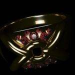
As usual we’ll need to find reference images that we will use for building model, you can pick any piece of jewelry (doesn’t have to be jewelry, any object that is reflective or refractive will do) for our practice. Please keep in your mind that different models will require different scene adjustments but the way to do it is always the same and even if you choose the same model, it could be that you will not get the result I got. The ring that you see is called ‘Trika’ from Bvlgari. I took it because it has everything that I need – nice forms, smooth and bump gold material and diamonds.
Now when we know what we will model, it is good to read about how professional photographers are making environments for jewelry presentations. It is good to read it because actually it will be easier for you when we start to build our scene to understand some terms, techniques etc.
Reference articles are:
Lighting Highly Reflective objects – Some explanations on controlling lights and shadows
Photo Tips for Metalsmiths – Here you will get some general information’s on terms and some basic knowledge on photography
Two Methods of Photographing Jewelry – Actual tips for building boxes for making jewelry photo’s
So now when we know some basics in photography we can start to think how we will transfer it to Max or any other 3D Application. I was using the standard scan line Max renderer, so the easiest was to use black background with light (faking real light boxes) reflections. If you are using some GI renderer you can get some really nice images on white (or any other solid color) background since you will have nice shades in metal reflection (glass refraction) and soft shadows. Similar technique was used for New Rider’s contest with a mighty renderer plug in called Brazil in an early stage of developing. If you know how to fake GI (Global Illumination) or you want to give it a shot I can only suggest to use gradients in material or light dome technique. Ok, I will not talk about something that I didn’t try first, but I would go this way.
Good reference images that shows how metal acts in a black environment and lights, can be seen at Bvlgari. look under jewelry section; Wedding Rings, Astrea, Corona
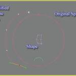
The easiest way to model the ring is lofting ![]() . Actually I created an N-gon for path and added an ‘Edit Spline’ modifier (I use it because if I mess something up, I can always erase this modifier only). The shape is ‘Rectangle’, also with an ‘Edit Spline’ modifier added and in Vertex sub-object we add few vertices. Keep in mind that we will add ‘Mesh Smooth’
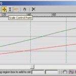
. Actually I created an N-gon for path and added an ‘Edit Spline’ modifier (I use it because if I mess something up, I can always erase this modifier only). The shape is ‘Rectangle’, also with an ‘Edit Spline’ modifier added and in Vertex sub-object we add few vertices. Keep in mind that we will add ‘Mesh Smooth’ ![]() modifier on the object so it is good that all segments are ‘lines’ and not ‘curves’. Depends on model, but in this example we need to adjust the size of the shape on different parts of the path. We do this in modify /loft/ Scale and in center we raise the value only on X (or Y) axis for let say 250 %. We will need to change vertices from ‘corner’ to ‘smooth’ and adjust it so that our model is smooth and not to have a broken look, also you will need to uncheck ‘Adaptive Path Steps’ in the Loft modifier.
modifier on the object so it is good that all segments are ‘lines’ and not ‘curves’. Depends on model, but in this example we need to adjust the size of the shape on different parts of the path. We do this in modify /loft/ Scale and in center we raise the value only on X (or Y) axis for let say 250 %. We will need to change vertices from ‘corner’ to ‘smooth’ and adjust it so that our model is smooth and not to have a broken look, also you will need to uncheck ‘Adaptive Path Steps’ in the Loft modifier.
The top of ring was made with the box modeling technique and the round hole was made in loft. Later added ‘Edit Mesh’ modifier to be able to adjust vertices on the ends. Otherwise we will have a perfect look, not very good for realism. Added some bevels and some deformations as ‘Bend’ ![]() .
.
– On all four elements ‘Mesh Smooth’ ![]() was applied.
was applied.
So now we still need to adjust the shape of the actual ring. You can clone it and hide it just in case that something goes wrong. First we select the N-Gon shape and erase half the spline. We also have to adjust the loft scale since the vertex that has a value of 250 % is on center and we need it on the end (Pic.2). We mirror a ‘reference’ object (before that operation it is good to have the pivot point of the ring centered by Y axis and on the end on X axis) and on the reference object we add ‘Mesh Smooth’ so that we can work on the simpler object and see the results on the final object. Once you are satisfied with the look just clone the object and hide it, cut ‘Mesh Smooth’ from reference object, make it unique and attach to the first half (object). Now you’ll need to erase Polygons on joint and join vertices on that joint. Now is a good time to paste ‘Mesh Smooth’ on our object that you cut from the reference object.
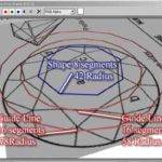
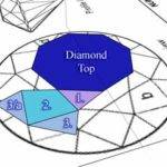
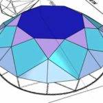
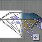
Diamonds are made in let say ‘real time modeling’. It sound very complex but in this case it is quite easy. First we have to find a blue print or reference image of a diamond. (Here is copy what I made). There are several shapes of gems, I took the classic diamond shape, also called the ’round’ shape. So the second step is to setup reference images and start to draw shapes in top view. I started with a top 8-gon because then I will have a perfect center for later use, then I clone it and fit it to the outlines in our reference image and instead to be 8-gon, I turned it to a 16-gon. Now we will clone our 16-gon and adjust the size so that it fits the intersection of our reference image. (we will use those two 16-gons as guideline only to have perfect geometry) Pic.4
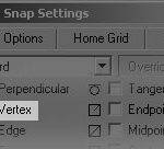
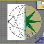
Now we activate 3D Snap ![]() (vertex snap is important, see Pic.5) and start to draw lines for our shapes. Of course we need to close spline when we are asked. Take a look at the Image (Pic.6) to see what shapes we have to build. Once the shapes are done you can turn them into meshes (Right click/Convert To Editable Mesh). We need to select meshes 1., 2., 3.,3.a and start to use the Diamond Top (mesh) as ‘Transform Coordinate’
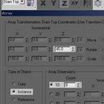
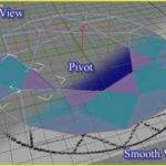
(vertex snap is important, see Pic.5) and start to draw lines for our shapes. Of course we need to close spline when we are asked. Take a look at the Image (Pic.6) to see what shapes we have to build. Once the shapes are done you can turn them into meshes (Right click/Convert To Editable Mesh). We need to select meshes 1., 2., 3.,3.a and start to use the Diamond Top (mesh) as ‘Transform Coordinate’ ![]() (you should have the pivot in center of diamond top) (Pic.7). Now we will array it as instance object 8 times in 45 degree. So far top part of diamond in top view is finished. The next step is to add a third dimension (height) and we will do it from ‘Left’ or ‘Front’ View or to say on absolute Z axis. First we have to adjust the reference image so that widths are fit with our object and then we chose only one shape and adjust the vertices according to reference image. When the top is finished (Pic.9) you should select shape 3 & 3/a and then mirror it to the bottom. New meshes must be aligned to bottom side of top faces and then again array them as we did before. The next step is to adjust bottom vertices ( Pic.10). Now we will use our guideline 16-gon again. We will rotate it 22.5 degrees (or any other degree that coordinate system is orthogonal/parallel with our new shape) and use it as our ‘Transform Coordinate’
(you should have the pivot in center of diamond top) (Pic.7). Now we will array it as instance object 8 times in 45 degree. So far top part of diamond in top view is finished. The next step is to add a third dimension (height) and we will do it from ‘Left’ or ‘Front’ View or to say on absolute Z axis. First we have to adjust the reference image so that widths are fit with our object and then we chose only one shape and adjust the vertices according to reference image. When the top is finished (Pic.9) you should select shape 3 & 3/a and then mirror it to the bottom. New meshes must be aligned to bottom side of top faces and then again array them as we did before. The next step is to adjust bottom vertices ( Pic.10). Now we will use our guideline 16-gon again. We will rotate it 22.5 degrees (or any other degree that coordinate system is orthogonal/parallel with our new shape) and use it as our ‘Transform Coordinate’![]() for the vertices’ movement. There is only one more shape to be done, so let’s do it. We should assign in 3D Snap
for the vertices’ movement. There is only one more shape to be done, so let’s do it. We should assign in 3D Snap ![]() ( ‘Center Face’ snap should be activated) because we will start to draw line from center of ‘Top Shape’ and later adjust all shape vertices according to vertices of our 4th shape ( Pic.11). When this is done we should also convert it to mesh and rotate array it 8 times. Now you should have your diamond done. Next step is to make every mesh unique to attach all meshes together and to weld all vertices.
( ‘Center Face’ snap should be activated) because we will start to draw line from center of ‘Top Shape’ and later adjust all shape vertices according to vertices of our 4th shape ( Pic.11). When this is done we should also convert it to mesh and rotate array it 8 times. Now you should have your diamond done. Next step is to make every mesh unique to attach all meshes together and to weld all vertices.
You should have a total of 41 vertices in the mesh.
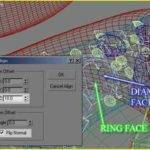
Diamonds were aligned with ‘Normal Align’ tool. You select diamond, click on the tool, then you will need to click on the diamond top polygon and then on the ring.
So far you should have a descent Model. Please keep in mind that I didn’t want to go step by step for something that you can always find in Tutorials that came with Max or that you can find on internet. I will give you some very good links to tutorials that can help you in modeling at the end of this page.
After all you should model it with the technique that best fit you.
This is part that will give our model color and shine {:o)) There are different colors (Hues) of gold, from almost white green to bronze red. It is up to you to choose which. The second ring is not made in silver but in white gold so it has a look of chrome.
Gold and Chrome are almost the same material that ships with 3DMax. So instead of making a bunch of snapshots, I give you link so you can download it. However, I will try to explain how/why I did it.
The difference in my materials is that I used Falloff/Fresnel reflection. Fresnel is actually the way to point the amount of reflection/refraction on the side and front of object. The IOR is 20.
On this ring I also combine smooth and bumpy gold/chrome with a Blend material. In smooth gold I added the same bitmap that I used in Blend for bump map (Pic.15).
The Light Box material is a bit tricky so I will explain how I did it. If you take a second look on any photo where there’s gold you can see that the reflection is actually yellow everywhere except where we have a light box. There we have white reflection. To achieve this we will force light box by adding ‘output’ material modifier in the ‘diffuse’ map . The same thing is done in Brazil when you make geometry lights.
Diamonds produce kind of pure refraction. We should exclude all gold and metal objects in ray calculation by clicking ‘Local Exclude’ in ‘Ray Tracer Controls’. So the only colors that will refract is white and black. I followed the rule ‘if it looks good, it is good’.
This is the most important step in our creation. If you make some test renders you will see that we don’t have something similar to the picture on top of this tutorial. This is because we don’t have a good environment setup yet.
First we determine position and rotation of the model(s). It is good if we make this as perfect as possible, all later adjustments of camera or objects will affect our image (reflections). Next step is creating light boxes, these are just ‘planes’ objects with already prepared material. Right position and rotation of the planes is very important. The easy way to control position is to create an omni light, align the omni to the center of the plane (on all 3 axis) and then link
the plane to the light. With tool
‘Place Highlight’ we choose our light and in camera view we assign it on desirable place (face) of object. Now we can make some test renders to see if the light box position and rotation is ok. If not, adjust rotation and position of plane first.
TIP: If reflection of a round object should be almost at the end, then you will have to rotate the plane in that direction. As you can see on Pic24. & Pic.25
It depends on the object, but you will need approximately 2-4 such light boxes in your scene. Adjust only one at the time until you are satisfied and then adjust the next one.
In my opinion you need to show contours of the object(s) but also some part of the object must be clearly visible. The sample (Pic.20) shows you that contours are good, but actually you don’t see anything else. So we have to add one light box on the left side and one on the right side (on Pic.24 & Pic.25 rotated big planes are what we need). It is hard to me to explain, but from images on your left side you will understand how rays travel from lights to object and then towards the camera. You only have to know that the angle of a ray entrance is the same as a reflected ray, mirrored. In other words, if the ray is hitting from left at 45 degrees, it will be reflected at 45 degrees to the right side. On oval models things are get more complex but the rule is basically the same.
TIP: If your light box, for some reason, is seen by the camera in your scene you can disable it by right clicking on the object, choose properties and uncheck ‘visible by camera’
Now you are pretty close to the end. Only a bit of Video post effect such as Glow and that should be it.
TIP: It can be helpful to render whole scene in *.RPF or *.RLA format and to save all necessary channels so that you will be able to use it later in ‘Video Post’
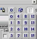
We will use Glow effect that comes with 3Ds Max as a standard plug in. We will apply glow on the Light Boxes as material effect so we will be able to get this effect in our reflections/refractions. Open Material Editor and assign ‘material ID’ (Pic.26) on our light box material. It is good to have unique material for every light box for better control. So if we have 4 lights then we should copy light box material 4 times add number in name and apply different material ID.
We go back to Video Post and add Glow effect for every light box and put desirable values. In my case it was only two:
Effect ID: 3 – Should be a Light Box material ID
Filter: All
Color: Pixel
Pixel Size: 3.0
Intensity: 0.4
And:
Effect ID: 2 – Should be a Light Box material ID
Filter: All
Color: Pixel
Pixel Size: 3.0
Intensity: 1
Now you should have your image done. Open your favorite photo software and just add your name 😉
Hope that this tutorial has learned you something, even though this is not a step by step tutorial. It was made for the3dstudio and the guys from the forum. In the near future I will also post a scene that has prepared environment but until then just keep on practicing.
Thanks to Johan Fröjd who made check before this tutorial was published.
Dean Kezan © 2001
To be added 😉
